 Crystallographic Topology 101

Introduction
The intended reader, or browser, is the crystallographer curious about how geometric topology fits into crystallography. Topologists curious about crystallography may find the presentation naive, but different. We are seeking crystallography and topology collaborators with related interests to build an interactive crystallographic topology web data base.
For our purpose we will say that crystallography is the study of atoms in crystals, topology is the study of distortion-invariant connectivity properties of mathematical objects, and crystallographic topology is an intersection of those two disciplines. Since both topology and crystallography have many subdisciplines, there are a number of quite different intersection regions that can be called crystallographic topology; but we will confine this discussion to one small, well delineated subarea.
The structural crystallography of interest involves the group theory required to describe symmetric arrangements of atoms in crystals, and a classification of the simplest arrangements as lattice complexes. The geometric topology of interest is the topological properties of crystallographic groups, represented as orbifolds, and the Morse theory global analysis of critical points in symmetric functions. Here we are taking the liberty of calling global analysis part of topology.
Our basic approach is that of a geometric crystallographer who finds the pictorial reasoning tricks of geometric topology reasoning intriguing. Other crystallographers prefer equations and would probably use algebraic topology concepts such as homology, which we seldom mention past this point. Being physical scientists rather than mathematicians, we emphasize only what we feel aids physical insight or provides computational automation possibilities while avoiding the use of theorems and mathematical proofs.
In the working crystallography laboratory, the universal fundamental reference is the series called the International Tables for Crystallography (ITCr). This series was started in 1935 and is periodically updated and expanded. The current edition is sponsored by the Commission on International Tables of the International Union of Crystallography. Volume A, Space-Group Symmetry (Hahn, 1995), is the chief source for the crystallographic material in the following discussion.
It is our hope that the discipline of "Crystallographic Topology" will eventually mature in completeness and usefulness to justify the addition as a separate volume on this subject in the ITCr series. To help this happen, we welcome the collaboration of crystallographers and topologists to expand the following exploratory Crystallographic Topology 101 treatment and the incomplete Crystallographic Orbifold Atlas appendix into an unofficial but comprehensive treatment of the subject to be maintained on the World Wide Web as an interactive reference source freely available to everyone. An editorial on electronic publishing from the viewpoint of a topologist provides some interesting thoughts on the subject.
Organization of Topology 101 Material
There are a number of crystallographic and topological concepts that lead to the following mappings of structural crystallography onto geometric topology. Only the first two of the three lines are discussed here.
The current Sect. 1 provides an overview and illustrates a simple critical net, orbifold, and critical net on orbifold based on the sodium chloride (rock salt) crystal structure. Following a review of relevant orbifold references, Sect. 2.1 continues to illustrate and classify the 32 elliptic 2-orbifolds derived from the crystallographic point groups and shows how elliptic 2-orbifolds can be used as construction elements to build the singular sets of Euclidean 3-orbifolds. Sect. 2.2 illustrates basic topology surfaces, derivation of all 17 Euclidean 2-orbifolds from crystallographic drawings of the plane groups, and example derivations of Euclidean 3-orbifolds by lifting Euclidean base 2-orbifolds. Sect. 3 describes the Morse functions used and shows additional critical net examples, using stereoscopic illustrations, and summarizes their characteristics. Sect. 4 illustrates the derivation of critical nets on orbifolds, their presentation in linearized form, and the derivation of a symmetry-breaking family of cubic lattice complexes on orbifolds. The crystallographic lattice complex model as modified for critical nets on orbifolds is discussed in Sect. 5, and additional sets of cubic space group orbifolds are illustrated. The overall structure of the cubic space group families is summarized in Sect. 6.
Appendix A discusses the color crystallographic groups, which have both symmetry and antisymmetry elements. A color-blind reading of a bicolor group (Shubnikov group) produces a crystallographic group, and the black symmetry elements alone produce a normal subgroup. The 65 color elliptic 2-orbifolds derived from the relevant color point groups are listed and classified as a pairwise extension of the classification used for the regular elliptic 2-orbifolds in Sect. 2.1. Point group/subgroup relationships are then depicted in graphical form. Using Wyckoff sites for 3-D bicolor space groups tabulated by Koptsik, an example in Appendix A illustrates an alternate approach, one more suitable for computer automation, for the derivation of Euclidean 3-orbifold symmetry breaking families. The graphic color elliptic 2-orbifold symbols shown in Appendix B may be used in the construction of orbifold covers.
The Crystallographic Orbifold Atlas (in preparation) will eventually provide a full tabulation of those topological properties of crystallographic orbifolds that seem potentially useful to crystallographers. We have basic results covering most of the space groups but have not found an optimal format for their presentation. At present, only the "A" family of cubic space groups and one hexagonal space group are discussed in the Crystallographic Topology 101 tutorial.
Why Critical Nets?
We sincerely believe that critical-net and critical-net-on-orbifold crystallographic illustrations will some day be of fundamental importance in crystal chemistry and crystallographic topology. Critical nets are based on the concepts of Morse functions, Morse theory (i.e., critical point analysis), and hyperplane arrangements in topological complexes, which are classic topics in the mathematical topology and global analysis literature. Morse functions on orbifolds constitute a relatively new aspect of equivariant (i.e., group orbit compatible) topology.
Critical Points
Our ORTEP-III computer program
can produce "critical net" illustrations that depict some canonical
topological characteristics of the ensemble of overlapping
atomic-thermal-motion Gaussian density functions in a crystal. Only
non-degenerate critical points are considered here since a degenerate
critical point can always be distorted into a set of non-degenerate
ones through a process known as "morsification" (Dimca, 1992).
In addition, we have
so far not found a true degenerate critical
point in a valid crystal structure and have a working hypothesis
that all crystal
structures are Morse (Marston Morse) functions (i.e., they have no
degenerate critical points). Critical points occur where the first
derivative of the global density is zero. The second derivative at
that point is a 3  3 symmetric matrix, which has a
non-zero determinant only if the critical point is non-degenerate . The
signs of the three eigenvalues of the second derivative matrix specify
the types of critical points, which we term peak (-,-,-), pass (+,-,-),
pale (+,+,-) and pit (+,+,+). A degenerate critical point will have a
singular second derivative matrix with one or more zero or nearly
zero eigenvalues.
3 symmetric matrix, which has a
non-zero determinant only if the critical point is non-degenerate . The
signs of the three eigenvalues of the second derivative matrix specify
the types of critical points, which we term peak (-,-,-), pass (+,-,-),
pale (+,+,-) and pit (+,+,+). A degenerate critical point will have a
singular second derivative matrix with one or more zero or nearly
zero eigenvalues.
The critical points are best described as representing 0-, 1-, 2-, and 3-dimensional cells in a topological Morse function CW complex (i.e., C for closure finite, W for weak topology). We use a "critical net" representation that has unique topological "separatrices" paths joining the critical point nodes into a graph. We will sometimes denote the peak, pass, pale, and pit critical points with the numbers 0, 1, 2, and 3, respectively. The most gradual down-density paths from a peak to a pit follow the sequence peak -> pass -> pale -> pit. These paths, shown by the separatrices (i.e., "connection bonds") in Figs. 1.1 and 1.2, are topologically unique. This uniqueness arises because: (a) the pass and pale critical points each have one unique eigenvector connecting to the separatrices going to one peak and one pit, respectively, and (b) there are two-dimensional hyperplanes connecting to the two remaining eigenvectors of each pass and pale and these non-parallel hyperplanes intersect each other locally to form the pass-pale separatrices. Additional examples are given in Sect. 3.
We postulate that there are no bifurcated (forked) separatrices or degenerate critical points in the crystallographic critical nets of interest here. In experimentally derived crystallographic macromolecule electron-density functions, this will not be the case because of critical point merging caused by inadequate resolution experimental data. Theoretical quantum chemistry results may also lead to exceptions because of added "quantum quirk" topological features.
Critical Net for NaCl
Fig. 1.1 is an ORTEP-III critical net illustration for one octant of the NaCl unit cell contents with the larger corner spheres representing Cl peaks; the smaller corner spheres, Na peaks; the cigar-shaped ellipsoids, passes; the pancake-shaped ellipsoids, pales; and the smallest sphere in the center, a pit. The reason for this choice of shapes for the pass and pale saddle points is that the passes and pales represent edges and faces, respectively, for convex polyhedra in special cases such as NaCl. Non-polyhedral counterexamples are discussed in Sect. 3.
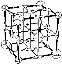
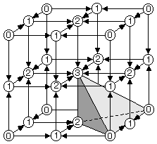
Fig. 1.2 shows the critical point (0=peak, 1=pass, etc.) locations in one octant of the unit cell for NaCl. A sodium ion is on the peak site in the lower right front, and a chloride ion is on the peak site in the lower right rear. The vectors in Fig. 1.2 point downhill, in a density sense, along the topologically unique paths of the critical net.
NaCl crystals have the internal symmetry of space group
Fm m, which is
No. 225 in the International Tables for Crystallography (Hahn, 1995).
There is a lot of symmetry in this group; thus the general position
multiplicity within the cell is 192, which is the largest multiplicity
possible in the space groups. Points on symmetry elements have
smaller total unit cell occupancy, called the Wyckoff site
multiplicity. Thus there are only 4 Na + 4 Cl peaks, 24 passes, 24
pales, and 8 pits in the unit cell. The shaded tetrahedron in Fig.
1.2 is an asymmetric unit (fundamental domain) of the unit cell,
which occupies 1/24 of the volume shown and 1/192 of the unit cell
volume.
m, which is
No. 225 in the International Tables for Crystallography (Hahn, 1995).
There is a lot of symmetry in this group; thus the general position
multiplicity within the cell is 192, which is the largest multiplicity
possible in the space groups. Points on symmetry elements have
smaller total unit cell occupancy, called the Wyckoff site
multiplicity. Thus there are only 4 Na + 4 Cl peaks, 24 passes, 24
pales, and 8 pits in the unit cell. The shaded tetrahedron in Fig.
1.2 is an asymmetric unit (fundamental domain) of the unit cell,
which occupies 1/24 of the volume shown and 1/192 of the unit cell
volume.
Orbifolds
As Walt Kelly's philosophical comic-strip character Pogo might have said, "The trouble with symmetry is that it's repetitious". Orbifolds remove all repetition; thus all space-group orbifolds will have roughly the same size and complexity, a situation that contrasts sharply with traditional crystallographic geometric drawings of space group symmetry as given in the International Tables for Crystallography (Hahn, 1995).
A crystallographic orbifold, Q, may be formally defined as the quotient space of a sphere, S, or Euclidean, E, space modulo a discrete crystallographic symmetry group, G (i.e., Q=K/G where K=S or E). G is one of the ordinary 32 2-D point groups if K is a 2-sphere, one of the 17 2-D plane groups if K is 2-Euclidean, or one of the 230 3-D space groups if K is 3-Euclidean. The term elliptic is used rather than spherical because the projective plane is involved (Thurston, 1990) (see Sects. 2.1 and 2.2). In the present discussion, we have no need to generalize into dimensions higher than three or to utilize hyperbolic orbifolds.
Another viewpoint is that an orbifold is a compact closed quotient space that results when all equivalent points are overlaid onto one parent point. In contrast to the orbifold's closed space, the crystal space is an open (infinite) Euclidean 3-space. For the space groups, a reasonable working definition is that a properly bounded fundamental domain within a space group's unit cell is an orbifold. For the special case of a fundamental domain bounded by mirrors, the fundamental domain is itself an orbifold.
Orbifold for Space Group Fm
Fig. 1.3-left shows the 3- and 4-fold rotational symmetry axes
within an octant of the unit cell for Fm
The topological information for the tetrahedral Euclidean 3-orbifold of
NaCl is expressed more economically in the skeletal
drawing shown in Fig. 1.4-left, in which the viewer is positioned directly
above an apex of the tetrahedron.
The mirror locations are indicated by
the symbol 1' with the mirror for the bottom hidden face indicated by the
cornered 1' over the tetrahedron. Every axis marked with a prime,
such as 4', has to have two adjacent mirror planes and every corner
point, such as 2'2'2' (inferred from the axes' intersections),
has to have three adjacent mirror planes. Thus,
we can interpret the skeletal tetrahedron details almost as easily as
the double line mirror symbol drawing in Fig. 1.3.
The Rubber Sheet World of Topology
An artist can exercise artistic liberties to emphasize desired features
in a picture, but a topologist can and does exercise even more
topologic liberties in his rubber sheet world where any deformation is
perfectly acceptable as long as you do not tear anything (Barr, 1964). When
topologists read the old warning label on computer punched cards, "do not
fold, mutilate, or spindle", they probably only took the third item
seriously. (Webster dictionary definition of spindle - to impale, thrust
or perforate on the spike of a spindle file).
Some of the topologists' favorite distortions of a rectangle are shown
in Fig. 2.5.
In that spirit, it is perfectly acceptable to deform
the tetrahedron into a sphere, as shown in the middle drawing, and put
the 3'3'2' dihedral corner and its attached 3' and 2' axes in the
upper hemisphere. This makes the underlying topological space, a
silvered 3-ball, more readily apparent.
The Wyckoff site list for Fm
For example, in Fig. 1.3-left a single straight
body-diagonal axis from a to b through the mirrored intersection of axes
c has two nonequivalent parts, ac and bc, while all even-ordered axes
repeat themselves about an intersection of axes.
Thus, what at first appears
to be two different axes along the top edges of the asymmetric
unit is in fact a single bent axis. A 3-axis can also wrap a
mirror around itself without breaking it.
Thus in Fig. 1.4-middle, the three mirror
segments in the upper hemisphere that are in contact with the 3-axis
are simply different parts of the same mirror. All orbifold mirrors
start and stop only at even ordered axes.
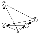
Linearized Critical Net on Orbifold
By superimposing Fig. 1.2-right onto Fig. 1.3-right, we obtain a
critical-net-on-orbifold representation, which is one of the main
topics of our presentation. Again taking a few topologic liberties, we
can deform the whole critical-net-on-orbifold silvered 3-ball to
arrange the peaks, passes, pales, and pits in sequence vertically down
the page as shown in the righthand bottom drawing of Fig. 1.4.
Thus, density decreases as you go down the page and we have
literally done the mapping E3 ->
E1, which is characteristic of Morse
theory. This
linearized critical-net-on-orbifold drawing still accurately portrays
the Euclidean 3-orbifold and NaCl critical net information and is
topologically correct. The symbols within the circles are lattice
complex symbols discussed in Sect. 5.
This critical-net-on-orbifold
drawing with the lattice complex information for each
critical point site added provides an excellent summary of the
structure's local and global topology, particularly if the Wyckoff site
multiplicities are also recorded on the same drawing as shown in
Sect. 4.
The advantage that orbifolds and critical nets on orbifolds provide is
a concise closed-space portrait of the topology for crystallographic
groups and simple crystal structures, respectively.
Question
Suppose you just joined the Crystallographic Topology Orbifold Ski Club,
and they sent you the ski trail map for twin peaked Rock Salt Mountain,
which by strange coincidence looks exactly like Fig. 1.4-right. If you
are a beginning skier and would prefer not to break your neck on your
first outing, which route should you take? If you are an olympic class
skier, which route would you take?
If ordinary skis are 2-dimensional, what is the dimensionality of
your Rock Salt Mountain skis?
Page last revised: June 3, 1996
 m
m,
and Fig. 1.3-right
shows the orbifold and its singular set using the orbifold nomenclature
discussed in detail in Sect. 2. Briefly, the
corner Wyckoff site (a), which has orbifold notation, 4'3'2', lies on
4-, 3-, and 2-fold axes running along its adjacent edges. All four
faces contain mirrors, as denoted by the primes on the numbers
and double lines in the drawing.
m
m,
and Fig. 1.3-right
shows the orbifold and its singular set using the orbifold nomenclature
discussed in detail in Sect. 2. Briefly, the
corner Wyckoff site (a), which has orbifold notation, 4'3'2', lies on
4-, 3-, and 2-fold axes running along its adjacent edges. All four
faces contain mirrors, as denoted by the primes on the numbers
and double lines in the drawing.
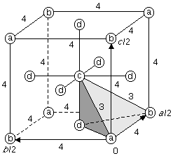
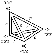
Figure 1.3. Euclidean 3-Orbifold for Space Group Fm
m.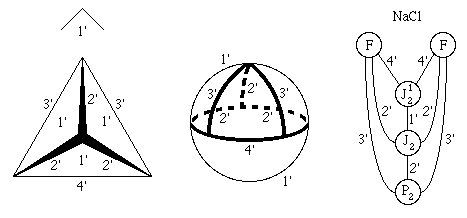
Figure 1.4. Fm
m Orbifold and NaCl Critical Set on Orbifold
Representations. m
in the ITCr tells us there are two
mirrors, three 2' axes, one 3' axis, and one 4' axis. Yet in Fig. 1.4-middle,
it appears these numbers should be
4, 3, 2, and 1, respectively. So what is going on?
The answer is that a 3-fold axis can do strange and wondrous things
simply because it is an odd-order axis, the only one in
crystallography.
 2.1. Elliptic 2-Orbifolds from Point Groups
 Crystallographic Topology Home Page