The X3B1 station is illustrated schematically below. Synchrotron
radiation from the NSLS bending magnet has a continuous spectrum with a
critical energy of 5.6 keV (2.23Å critical wavelength) when the ring
is operating at 2.584 GeV (7.1 keV or 1.75Å at 2.8 GeV). There is
useful intensity at this unfocused beamline up to about 40 keV. The X3B1
monochromator, approximately 12 meters from the source point, consists
of a pair of parallel Si(111) crystals mounted on a rotation stage, with
provision to adjust the gap between them and for coarse (DC motors) and
fine (piezoelectric translator in a feedback loop) angular alignment of
the two crystals. The first crystal, which receives a heat load of about
20 watts of x-ray power, is cooled by water. The monochromator operates
in an atmosphere of purged helium gas, separated from the storage ring
by a Be window, and from the experimental hutch by a thin kapton window.
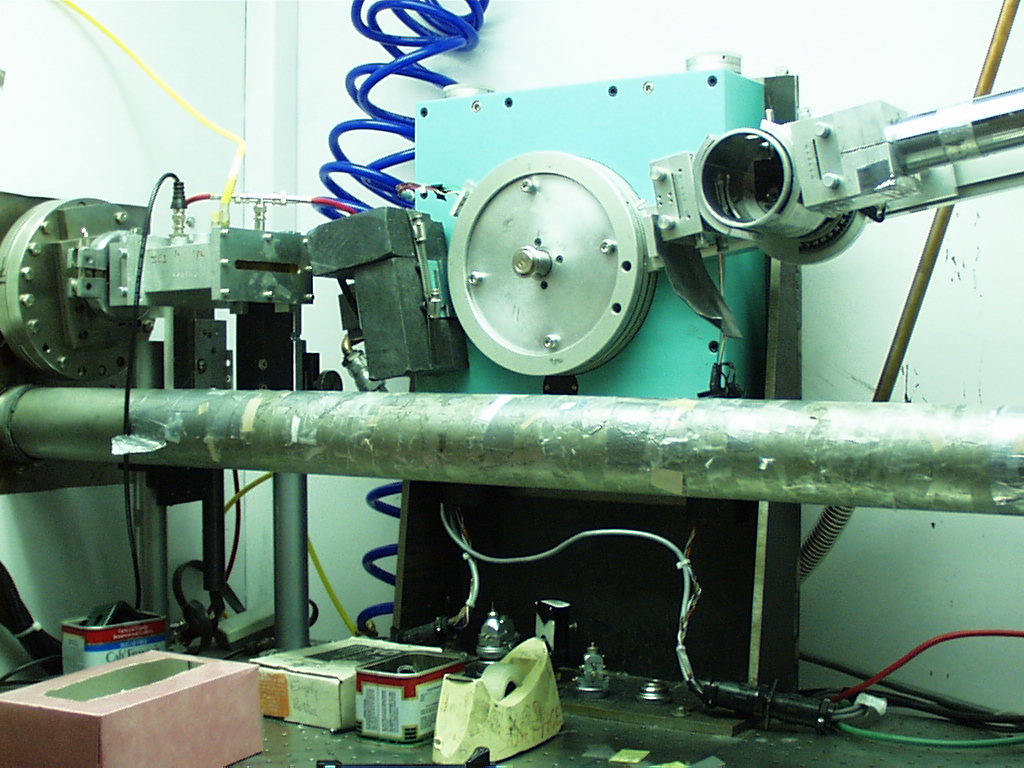
The beam enters the experimental hutch, where it passes collimating slits (typically 2mm vertical by 8mm horizontal), an ionization chamber monitor for the incident flux, and strikes the sample on a Huber model 424 Q -2Q diffractometer. This is mounted in a vertical plane, with the rotation axes horizontal, to match the diffraction geometry to the intrinsically small vertical divergence and horizontal polarization of the synchrotron radiation beam. The diffractometer can hold a variety of sample environmental chambers, so that measurements can be performed with sample temperatures in the range 15K to 400C. Samples are easily accommodated in either a flat plate geometry (usually on quartz zero-background holders) or in sealed capillaries.
The beamline can be operated in two different modes of diffracted beam resolution. In the (usual) high resolution mode, the x-rays diffracted from the sample pass another set of adjustable slits and strike the analyzer crystal, typically Ge(111) or Ge(220). This diffracts the beam into a commercial NaI scintillation counter. The analyzer crystal geometry gives the instrument a very fine angular resolution, on the order of 0.01° full width at half maximum (FWHM) at small Bragg angles 2Q . The diffraction peaks become sharper at shorter wavelengths, so that the overall d d/d resolution is roughly independent of wavelength. It is a rare sample that produces instrumental resolution limited peaks in this configuration. This high resolution is very useful for separating closely spaced diffraction peaks, and often provides a much better signal to background ratio than a conventional laboratory powder diffractometer. Also, the analyzer crystal discriminates against x-ray fluorescence from the sample (although it can contribute its own fluorescence when operated above the Ge edge at 11.1 keV). In the low resolution mode, the diffractometer is equipped with a Söller collimator which produces diffraction peaks with approximately 0.03º FWHM. This has much greater throughput than the analyzer crystal, and so is better for detecting weak signals. However, the discrimination against sample fluorescence is generally much worse, because it depends on the quite poor energy resolution of the detector. In some cases, it may it advantageous to use our AmpTek Si diode detector, which has an energy resolution of a few hundred eV, but a rather small active area (13 mm2) and count rate (<1000 cps).
A secondary advantage of both the crystal analyzer and Söller collimator setups derives from the fact that they directly measure the angle of propagation of the diffracted x-ray, irrespective of its point of origin in the sample. This stands in contrast to the usual receiving-slit geometry, which is subject to various aberrations such as sample transparency, and to diffraction peak shifts if the sample is not carefully aligned.
The figure below shows a typical scan of a standard sample of LaB6 in crystal analyzer mode. Why does it have such an asymmetric shape? The cone of diffracted intensity intersects a straight slit, with the edges appearing at lower diffraction angle than the center. (This is even true for a "slit" in momentum space, such as provided by the crystal analyzer.) It is not hard to account for that effect, and the fitted lineshape is shown on the same plot. The geometry and predicted lineshape are worked out in Ref. 2. Some modern Rietveld analysis programs, such as FULLPROF and GSAS incorporate the correct geometry, which is important for the correct analysis of high resolution powder diffraction spectra.
Do you think that synchrotron powder diffraction might be just
the ticket for your problem? We are very interested to talk to you and
see if we can help. There are several ways this might work.
Whenever work at this beamline is published, it MUST contain
the following acknowledgment:
"Research carried out in part at the National Synchrotron Light Source at Brookhaven National Laboratory, which is supported by the US Department of Energy, Division of Materials Sciences and Division of Chemical Sciences. The SUNY X3 beamline at NSLS is supported by the Division of Basic Energy Sciences of the US Department of Energy under Grant No. DE-FG02-86ER45231."