CELREF: Graphical Unit Cell refinement.
7th September 1999 E-mail from Jean Laugier
"Generally I should like to make some remarks about the cell parameters measurements:
-The precision of the refinement of the cell parameters are not
proportionnal to the number of peaks treated by the program. It is always
better, when it is possible, to use peaks above 45°, mainly because the
vertical divergence changes at this value. For a cubic structure, for
example, it is better to measure only one peak at the maximum Theta angle
than to use Celref with a lot of peaks, if the zero shift is weak or known!
-In the Least Square method it is assumed that the errors are random and in
an experimental diagram the errors are totally systematic! It is necessary
to be suspicious about the parameters precisions given by the program.
-The mathematical method does not work very well with cubic structures, if
the starting a value is very different of the true value. it is always
better to refine the zero shift in this case. (The batch bersion works in
ILL since 20 years and nobody saw that! Probably they never refine cubic
cells!).
Perhaps it would be necessary to make a special algorithm for the cubic case..."
| CELREF can be obtained off the web at the the LMGP (Laboratoire des Materiaux et du Génie Physique de l'Ecole Supérieure de Physique de Grenoble http://www.inpg.fr/LMGP/) program suite site at http://www.ccp14.ac.uk/ccp/web-mirrors/lmgp-laugier-bochu/ |
|
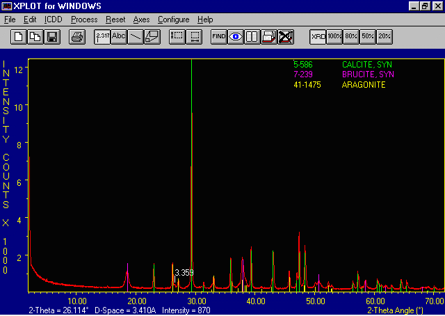
The example data file is of a Brucite, aragonite, calcite mixture. We will be
doing a unit cell refinement on the calcite.
|
|
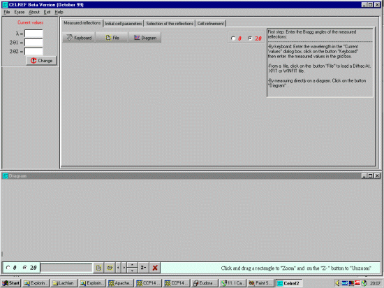
Click on the CELREF icon or run the program via the windows explorer/windows file manager to
bring up the CELREF starting interface.
|
|
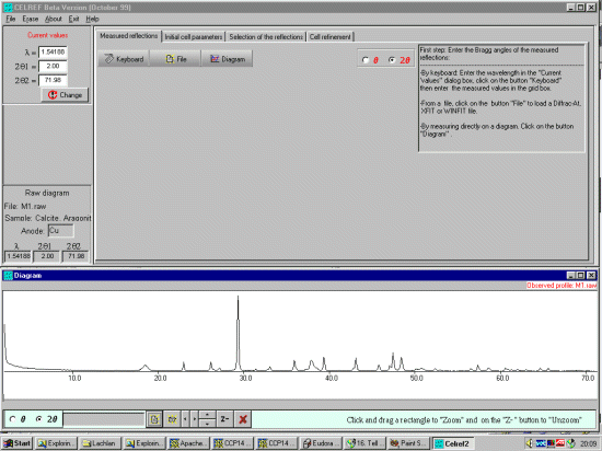
You can then open a Powder diffraction data file using either the
File, Open, Profile menu option or the the bottom left
hand set of ICONs (Celref can presently use Siemens/Bruker RAW, CPI or RIET7 DAT
raw datafiles).
|
|
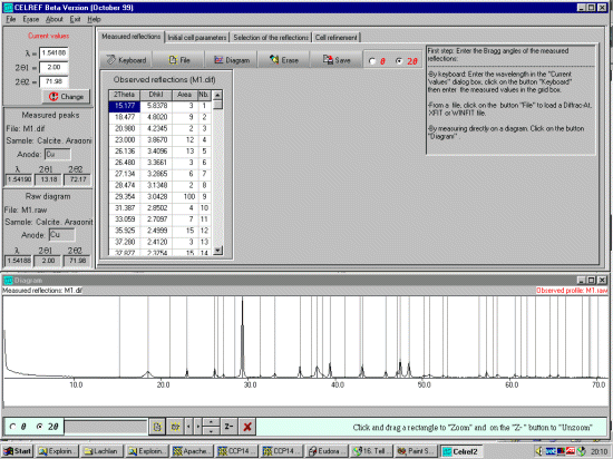
Either type the reflections in by hand or open a peak find/peak profile file
either via the File, Open, Peaks File or the ICON under the Measured Reflections tab.
The peaks will be displayed on the bottom window. (Celref can presently import Siemens/Bruker DIF,
Winfit *.DAT, or XFIT *.TXT peak find/peak profile output files). If loading an XFIT or related file,
CELREF will prompt for the Wavelength of the peak file (which will hopefully match that of the data).
|
|
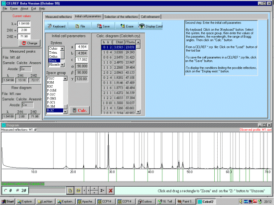
Select the Initial Cell Parameters tab. Input the (approximate) Cell, Spacegroup and calculation range information. (Cell, a=4.989, c=17.062; Spacegroup Hexagonal setting, R-3C, wavelength 1.54060, range 2, 72) and then press the Calc Button to generate the HKL listing. It is also possible to load this from a file if this information exists. Just click the File tab under the "Selected" Initial Cell Parameters tab.
|
|
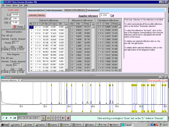
Select the Selection of the Reflections tab. To select the corresponding peaks, this can be done manually or automatically (with a controllable angular tolerance). Click on the Automatic Selection button to automatically select the corresponding peaks. Check both the top peak list and the bottom graphical representation to see that the selection has occured appropratiately. Peaks can be added or deleted manually. Be careful to check that Celref hasn't duplicated HKLs due to poor quality input data.
|
|
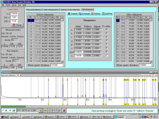
Select the Cell Refinement tab. At this point, recheck that the wavelength is correct, CELREF may be using the average alpha wavelength when you are profiled the peaks on the Alpha-1 wavelength. If you wish to change the wavelength, you can do this in the top left Current Values option area and click on the Red Change button. Click on the Compute button to perform the unitcell refinement. Two-theta offset can also be refined. If you click on this, Celref will prompt whether you wish to use model a constant zero shift or a sample exentricity. If you keep the unitcell constants at known values, the wavelength can be refined.
|
|
You can see all the results in a file using the Print ICON. Which is
normally outputted in a file called celref.out
----------------------------------------------------
Calcite (B thermiques bidon)maille hexa
----------------------------------------------------
 Number of reflections     :    19
 Max. number of refinement cycles   10
 Refinement constraints    : A=B

Initial values    :
   Zero  Lambda     a       b       c     alpha   beta  gamma
 .00000  1.54188  4.9940  4.9940 17.0820  90.00  90.00 120.00
   1.    0.       1.      0.      1.       0.     0.     0.

Recipr.lattice :   .2312   .2312   .0585  90.00  90.00  60.00
Volume (a**3)  :   368.949

 Number of refinement cycles       :     3


Final values      : (Standard errors on 2nd line)
   Zero  Lambda     a       b       c     alpha   beta  gamma
-.00079  1.54188  4.9942  4.9942 17.0768  90.00  90.00 120.00
 .00161   .00000   .0005   .0005   .0014    .00    .00    .00

Recipr.lattice :   .2312   .2312   .0586  90.00  90.00  60.00
Volume (a**3)  :   368.863

    H    K    L   2Th(obs)   2Th-Zero    2Th(Calc)     diff.

    0    1    2   23.000      23.000      23.008       -.007
    1    0    4   29.354      29.354      29.353        .001
    0    0    6   31.387      31.387      31.388       -.001
    1    1    0   35.925      35.925      35.922        .004
    1    1    3   39.370      39.370      39.361        .010
    2    0    2   43.106      43.107      43.110       -.003
    0    2    4   47.083      47.083      47.065        .018
    0    1    8   47.453      47.454      47.457       -.003
    1    1    6   48.453      48.454      48.456       -.002
    2    1    1   56.507      56.507      56.513       -.005
    1    2    2   57.344      57.345      57.348       -.004
    1    0   10   58.118      58.118      58.029        .089
    2    1    4   60.623      60.624      60.618        .006
    1    1    9   61.294      61.295      61.323       -.029
    1    2    5   63.000      63.001      63.002       -.001
    0    3    0   64.599      64.599      64.609       -.010
    0    0   12   65.524      65.525      65.561       -.036
    2    1    7   69.122      69.123      69.135       -.012
    0    2   10   70.172      70.173      70.189       -.016

Sqrt(Sum(Th O-C)**2)/(Nref-Npar)) =    .006602

Sqrt(Sum(2Th O-C)**2)/(Nref-Npar)) =    .003301
|
|
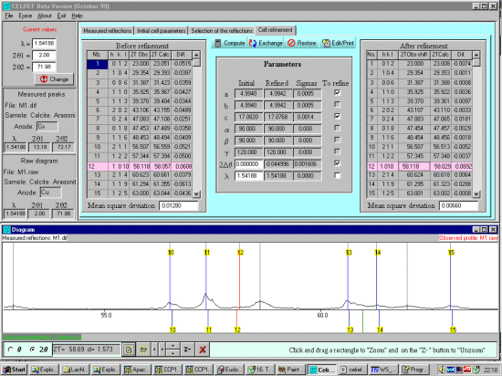
Looking at the output, you can use this as a guide to zoom up on areas to see if
profiled peaks may be mis-assigned. As is possibly the case with the HKL=1 0 10 peak.
Thus click on the HKL in the top right output window which will turn
the corresponding line in the plot window to red. Then you can zoom the
raw data plot and examine what could have happened graphically.
|